lv instrumentation diagrams | instrumentation loop diagram lv instrumentation diagrams P&IDs and loop diagrams are construction and documentation drawings that depict the flow of the process and illustrate the instrumentation control and measurement interactions, wiring and . In 1993, Omega launched the Seamaster Professional Diver 300M. With a blue wave-engraved dial, a scalloped bezel, lyre lugs, skeletonized sword hands, a sizable helium escape crown at 10 o’clock, .
0 · p&id instrumentation diagram
1 · instrumentation loop diagram
2 · instrumentation diagram abbreviation example
3 · instrumentation and control diagram
4 · industrial instrumentation diagrams
Dhs. 1,750.00. 30 Montaigne Phone Holder. Blue Dior Oblique Jacquard. Dhs. 4,700.00. 'CD' signature on the front 5 card slots Made in Italy The 30 Montaigne card holder presents an elegant and practical style. Crafted in blue Dior Oblique jacquard, it is embellished with the 'CD' signature on the front and features five card slots.
p&id instrumentation diagram
Typically instrument abbreviations used in P&IDs consist of two letters: the first indicating the process variable and the second indicating the instrument/controller function. For example, the . A P&ID could be a detailed flow diagram of the processing unit, ancillary unit, an offsite product storage system, product loading system, or it could be a drawing of the process .P&IDs and loop diagrams are construction and documentation drawings that depict the flow of the process and illustrate the instrumentation control and measurement interactions, wiring and .
P&ID diagrams (Piping and Instrumentation Diagrams) provide a schematic representation of the functional relationship between piping, instrumentation, and system .
instrumentation loop diagram
instrumentation diagram abbreviation example
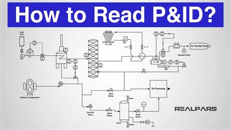
Definition: “A schematic diagram of the relationship between instruments, controllers, piping, and system equipment.” (Kirk, Weedon, & Kirk, 2014, p. 23) P&IDs are a symbol based schematic .To further understand instrument abbreviations used in instrumentation and process diagrams, we have presented more examples of the common combinations of instrument abbreviations you . The Process and instrumentation diagram, commonly known as a P&ID, shows the connections between process equipment. The diagram indicates the flow directions, safety .
Learn How to Read Piping and Instrument Diagram-P&ID, Process Flow Diagram and Block Flow Diagram used in Process Plant.
Typically instrument abbreviations used in P&IDs consist of two letters: the first indicating the process variable and the second indicating the instrument/controller function. For example, the instrument abbreviation “PI” denotes a “Pressure Indicator”. A P&ID could be a detailed flow diagram of the processing unit, ancillary unit, an offsite product storage system, product loading system, or it could be a drawing of the process and instrumentation system that connects different operating facilities together.P&IDs and loop diagrams are construction and documentation drawings that depict the flow of the process and illustrate the instrumentation control and measurement interactions, wiring and connections to the process. The process is illustrated in .
P&ID diagrams (Piping and Instrumentation Diagrams) provide a schematic representation of the functional relationship between piping, instrumentation, and system components within a project. They offer a detailed overview of the process flow, including equipment, valves, and instrumentation, crucial for design and operational understanding.Definition: “A schematic diagram of the relationship between instruments, controllers, piping, and system equipment.” (Kirk, Weedon, & Kirk, 2014, p. 23) P&IDs are a symbol based schematic language that once understood, adds simplicity to the information being presented. They can also be confusing when a unique symbol appears.
fendi calfskin regular monster peekaboo weighat
To further understand instrument abbreviations used in instrumentation and process diagrams, we have presented more examples of the common combinations of instrument abbreviations you may likely come across.
The Process and instrumentation diagram, commonly known as a P&ID, shows the connections between process equipment. The diagram indicates the flow directions, safety and control measures, and pressure ratings of a system through visual symbols.Instrumentation: The instrumentation includes sensors and other devices that measure process parameters like pressure, temperature, and flow rate. The information is used to provide feedback to the controller and ensure the desired flow rate is maintained. Below Table 3 shows some instrument abbreviations for devices like switches, alarms, transmitters, solenoids, relays, primary elements, test points, probe, view glass, as well as final elements. What do Tag Numbers on P&ID Diagrams represent?Learn How to Read Piping and Instrument Diagram-P&ID, Process Flow Diagram and Block Flow Diagram used in Process Plant.
Typically instrument abbreviations used in P&IDs consist of two letters: the first indicating the process variable and the second indicating the instrument/controller function. For example, the instrument abbreviation “PI” denotes a “Pressure Indicator”. A P&ID could be a detailed flow diagram of the processing unit, ancillary unit, an offsite product storage system, product loading system, or it could be a drawing of the process and instrumentation system that connects different operating facilities together.
P&IDs and loop diagrams are construction and documentation drawings that depict the flow of the process and illustrate the instrumentation control and measurement interactions, wiring and connections to the process. The process is illustrated in . P&ID diagrams (Piping and Instrumentation Diagrams) provide a schematic representation of the functional relationship between piping, instrumentation, and system components within a project. They offer a detailed overview of the process flow, including equipment, valves, and instrumentation, crucial for design and operational understanding.Definition: “A schematic diagram of the relationship between instruments, controllers, piping, and system equipment.” (Kirk, Weedon, & Kirk, 2014, p. 23) P&IDs are a symbol based schematic language that once understood, adds simplicity to the information being presented. They can also be confusing when a unique symbol appears.

To further understand instrument abbreviations used in instrumentation and process diagrams, we have presented more examples of the common combinations of instrument abbreviations you may likely come across.
The Process and instrumentation diagram, commonly known as a P&ID, shows the connections between process equipment. The diagram indicates the flow directions, safety and control measures, and pressure ratings of a system through visual symbols.
Instrumentation: The instrumentation includes sensors and other devices that measure process parameters like pressure, temperature, and flow rate. The information is used to provide feedback to the controller and ensure the desired flow rate is maintained.
instrumentation and control diagram
$2,995.00
lv instrumentation diagrams|instrumentation loop diagram


